Tag Archives: plastic gearbox

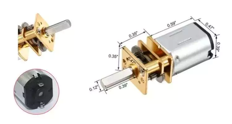
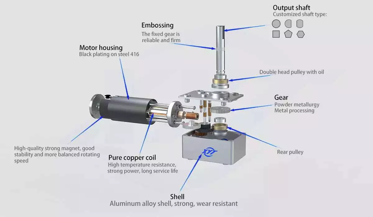
China 6mm 3v 5v 6v 12v 24v dc gear motor with plastic gearbox for smart locker double enveloping worm gearbox

Error:获取session失败,

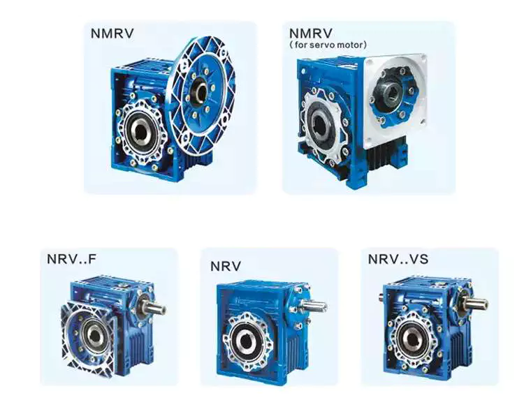
worm reducer

Worm gear reducer gearbox

A worm gear reducer gearbox is a mechanical device used to reduce the viscosity of fluids. It can be used in a variety of applications and is available in a variety of sizes. Read on to learn more about these devices. They come in different shapes, sizes and prices. Also, these products are very reliable.

Viscosity

A new study shows that polymers derived from worms reduce the viscosity of aqueous solutions. The researchers mixed the worms with water and then applied shearing force to the mixture. Polymer-filled solutions are more resistant to shear forces than simple liquids. This is because when the solution is sheared, the filaments become entangled with each other. When the solution is sheared, the filaments line up, reducing the viscosity of the solution.
The researchers then used live insects to study the polymer’s shear thinning properties. By measuring “worm activity”, the researchers could calculate the viscosity of the mixture. The researchers then altered the worms’ activity and measured changes in the viscosity of the mixture.
The PSMA13 precursor was synthesized from BzMA at 90 °C. The resulting PSMA13-PBzMA65 worms were studied using SAXS, 1H NMR and TEM. They were found to be highly anisotropic over a wide temperature range.
The efficiency of a worm gear reducer gearbox increases with the number of revolutions of the input shaft. Braking torque also increases with the viscosity of the oil. These three factors are used to determine the efficiency of a worm gear reducer gearbox. A worm gear reducer gearbox with a helical pinion on the motor shaft will achieve a 40:1 gear ratio. The combination of a 4 liter ratio helical primary gear with a 10:l worm secondary gear will achieve high efficiency and overload capability.
The PSMA13-PBzMA65 dispersion has the same effective viscosity at 20 degrees Celsius and variable temperature. The transition time is 0.01 Pa s, indicating good thermal reversibility.

Self-locking function

Worm reducer gearboxes have many advantages. This gear has a high capacity and can transmit a lot of power. It’s also very quiet. Its advantages also include a space-saving design. Another benefit of worm reducer gearboxes is their ease of lubrication and cooling. It is also an excellent choice for transmitting high power with high gear ratios.
The self-locking function of the worm gear unit ensures that torque is only transmitted in one direction. When the load peaks, the torque signal is disabled. Unlike conventional gear reducer gearboxes, self-locking worm gears are not interchangeable.
Self-locking worm gears are not suitable for high mass applications because the weight of the driven mass can overwhelm the gear. The large mass can cause a huge side load on the worm, which can cause the worm to break. To solve this problem, a self-locking worm gear train with special provisions can be designed to reduce the heat generated.
The self-locking properties of worm reducer gearboxes are helpful in many industrial applications. It prevents reversing, which saves money on the braking system. It can also be used to lift and hold loads. The self-locking function is very useful in preventing backing.
The self-locking function depends on the pitch diameter and lead angle. A larger pitch diameter will make the self-locking function easier. However, the lead angle decreases as the pitch diameter increases. The higher pitch diameter will also make the worm reducer gearbox more resistant to backlash.
Self-locking worm gears are also useful in lifting and hoisting applications. If the worm gear is self-locking, it cannot reverse its direction without positive torque.s This makes the worm gear ideal for applications where the worm must be lowered.
worm reducer

application

The worm gear reducer gearbox market is a global industry consisting of several sub-sectors. This report analyzes past and current market trends and discusses key challenges and opportunities in this market. It also highlights leading marketing players and their marketing strategies. Furthermore, the report covers important segments and provides information on emerging segments.
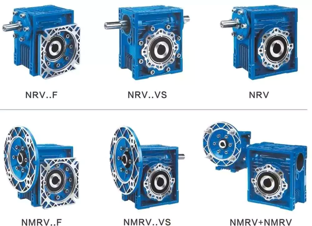
Worm reducer gearboxes can be used in a variety of applications, such as reducing the speed and torque of rotating parts. These gears are usually available as gear sets and seat units and are available in multi-speed designs. Some manufacturers also offer precision worms and zero-backlash worms for high precision reduction.
Typically, worm gears are used on vertical axes that do not intersect. Compared to other gear drives, they are inefficient but produce a lot of reduction. There are two basic types of worm gears: double envelope and single envelope. The difference is in how they work. When the two axes do not intersect, a double-enveloping worm gear is used.
In the industrial world, worm gear reducer gearboxes are the most popular type of reducer gearbox. They are known for their high torque output multipliers and high reduction ratios. They are used in many power transmission applications including elevators, safety gates, and conveyor belts. They are especially suitable for low to medium-horsepower applications.
Worm gears can also be used for noise control. Its unique shape and size make it suitable for tight spaces. They are also suitable for conveying heavy materials and the packaging industry. In addition, they have high gear ratios, which make them suitable for small and compact machinery.

cost

The cost of a worm gear reducer gearbox depends on several factors, including the type of worm used, the materials used to manufacture the equipment, and the number of users. The worm gear reducer gearbox market is divided into two types: vertical and horizontal. Furthermore, the market is segmented by application, including the automotive industry, shipping industry, and machinery and equipment.
Worm gear reducer gearbox is a popular type of reducer gearbox. They are available in standard and flush-type packaging. They feature C-side inputs for standard NEMA motors and multiple mounting positions to suit the application. For example, a soup factory can use the same hollow reducer gearbox in multiple installation locations.
Another application for worm gear reducer gearboxes is in conveyors. They provide torque and speed reduction to move products efficiently. They are also widely used in security doors that automatically lock when they are closed. Typically, these doors use two separate worm drives. In this way, they cannot be reversed.
The cost of a worm gear reducer gearbox is determined by several factors. Size and material are important. Worm gear reducer gearboxes can be made of aluminum, cast iron, or stainless steel. Its efficiency depends on its size and proportions. It is usually used as a retarder in low-speed machinery, but can also be used as a secondary braking device.
There are two types of worms: standard worm and double worm gear. Standard worms have one or two threads, and double worm gears have one left-hand and right-hand thread. A single-threaded combination will give you a 50 reduction ratio, while a dual-threaded combination will only give you a 25% reduction.
worm reducer

manufacturing

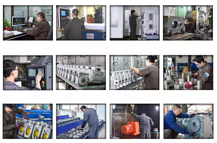
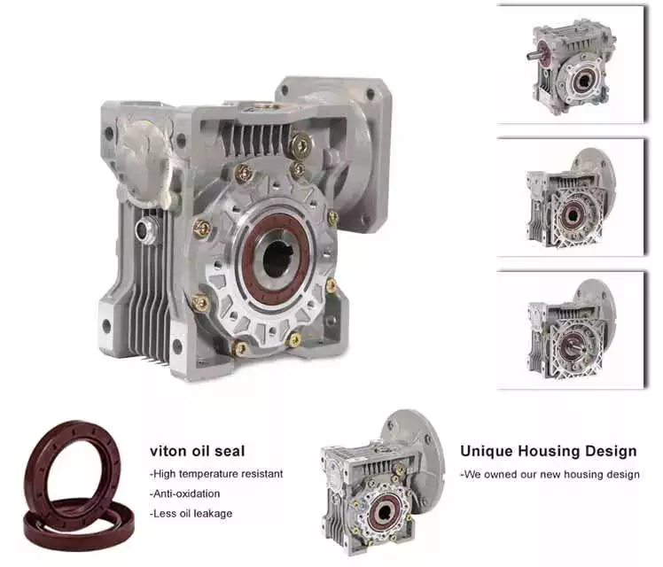
Agknx Transmission Ltd. manufactures premium worm gear reducer gearboxes with robust construction and premium case-hardened steel worms. They use phosphor bronze centrifugally cast rims and attach them to the output shaft in the center. They also feature dual-purpose bearings and a large overhang load margin on the output shaft. The high-quality reducer gearbox also has a full range of positive lubrication functions. This means that they do not need special attention when using low-speed shaft extensions.
China 6mm 3v 5v 6v 12v 24v dc gear motor with plastic gearbox for smart locker     double enveloping worm gearboxChina 6mm 3v 5v 6v 12v 24v dc gear motor with plastic gearbox for smart locker     double enveloping worm gearbox
editor by Cx 2023-04-27

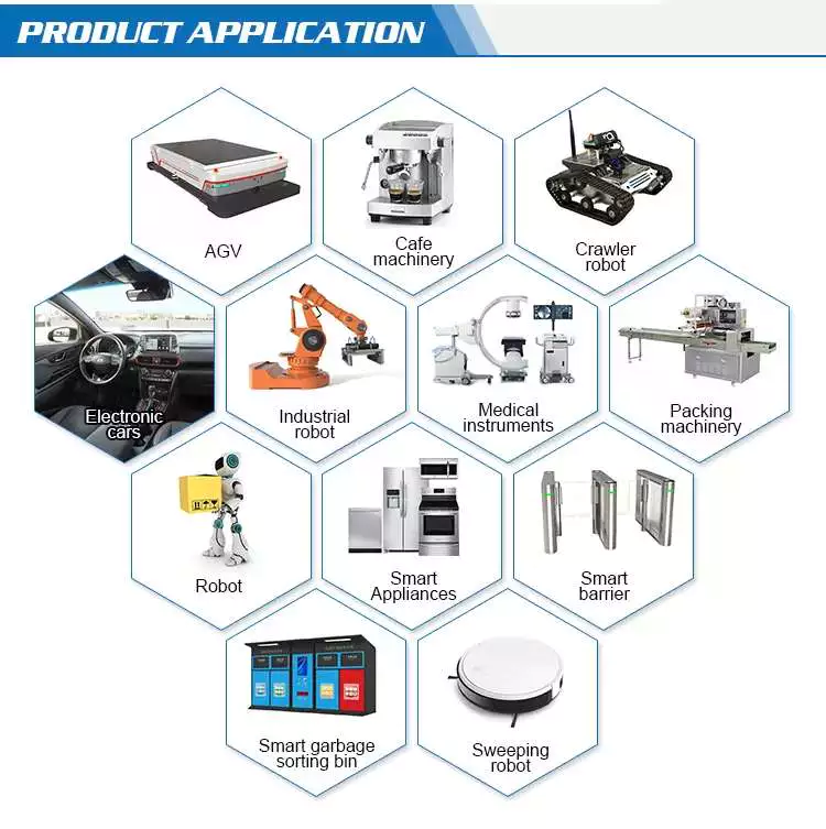
China ABS pa66+30gf Nylon POM Derlin super reducing running rear spur helical worm bevel ring plastic gear manufacturer worm gearbox application

Relevant Industries: Production Plant, Machinery Restore Outlets, Retail
Gearing Arrangement: Personalize
Output Torque: Customise
Input Pace: customize
Output Speed: Customise
Product name: Ab muscles pa66+30gf Nylon POM Derlin Plastic lowering gear boxes housing
Materials: Plastic POM Abs Nylon PA66+thirty%gf PA TPEE PPS
ISO certificates: IATF16949 ISO9001 ISO14001
Feature: Large precision minimal noise stable transmission
Benefit: 1-quit procurement
Processing: Plastic injection moulding
Product normal: JIS JGMA ISO DIN GB
Color: natural pink blue yellow white orange
Condition and measurement: for each customer’s dimension
Quality: one hundred% inspection ahead of packing
Packaging Information: Standard package deal: 1. Gears packed in plastic blister, and fill in master carton 2. Learn carton loading on pallets for shipment 3. Or buyer necessity
Port: HangZhou, China

  • OEM & ODM services, any tailored dimensions are offered, Make sure you supply portion drawing or sample for quotation.
    MaterialDerlin, POM, Nylon, TPEE, PA, Laptop, PEEK, PPS…
    CharacteristicGentle bodyweight large Precision, Low noise, stable functionality
    ColourOrganic coloration / Customized
    MeasurementCustomise, for every drawing or sample
    Manufacture processingMould Injection and machinery approach
    SampleCost-free available sample in hands spend the CZPT charge to get exact sample
    Sample guide timeforty days for CZPT building and samples
    Mass manufacturing guide time10-fifteen times dependent on the order amount
    Payment termsTT, L/C
    PackingPlasitc blister, ANSI standard C45 metal drive chain wheel roller idler sprocket 60B-13T Loafer Sprocket for Roller Chain 5-ply brown corrugated grasp carton and pallets, or Customized
    Shipping and delivery methodExpress shipping and delivery, air transport, sea shipping and delivery ect.

  • Hot Sale
  • Organization InformationWhy Decide on Us
    As a skilled ODM / OEM producer in exact equipment / gearbox, equipment CZPT in HangZhou metropolis, China for above ten a long time.
    We give one-stop services from gear/gear box style, equipment CZPT style, equipment CZPT generating, gear injection and equipment box assembly.
    We already obtained TS16949, ISO9001, ISO14001, and are China Nationwide Substantial-Tech Business given that 12 months 2015.
    R&D Team, factory price, large high quality, on time delivery pleased all our client in excess of the world.

  • Our Edge
  • twelve- Years Prosperous Knowledge in Equipment Transmission Industry
  • Lower Noise, Large Effectiveness, Steady Transmission
  • OEM & ODM Provider, 1-Cease Answer for Equipment and Gearbox
  • Substantial Top quality, 100% Inspection Just before Deal

  • CertificationsWe have obtained ISO9001, Manufacturing unit immediate income stainless metal sprocket industrial machinery transmission gear bearing add-ons ISO14001, IATF16949 certificates
  • Firm Lifestyle
  • Packaging & Shipping and delivery
    Common package deal : Plastic Blister + Master carton
  • FAQQ1: What kind of products Xinghuo can Provide?
    one. Higher precision plastic and steel gears with minimal noise, secure transmission
    two. Plastic equipment Injection mould
    three. Gearbox and gearbox assembly

    Q2: What is benefit of Xinghuo?
    Expert equipment and gearbox company in China Mainland, Established in the year of 2006. One-quit provider from gear R&D, gear style, gear CZPT build, gear manufacturing, and gearbox assembly
    We geared up Japan first HAMAI N60 CNC equipment hobbing devices, Switzerland unique AgieCharmilles C Axis EDM , MAKINO EDM, WEDM-LS, and Osaka JIS test centre, Osaka equipment mesh tester, concentricity tester, CMM, sound take a look at space and so on. Sophisticated services provide committed services to consumers.

    Q3: Why Choose Xinghuo in China?
    1. Expert R&D Team: provide most suited customize transmission solutions per application and customer’s requirement.
    2. Superb Quality Handle: Stick High quality management technique, 100% inspection /examination ahead of cargo.
    three. Excellent Soon after Sales Tracking Technique: Offer Each Images, Shipping and delivery and Advertising Information sharing.
    4. Quick response: revenue supply quick reaction inside 24 hrs for any quires.
    If you have yet another issue, pls truly feel totally free to speak to us as below:

  • Is a worm gear reducer gearbox right for your application?

    If you’re interested in gear reduction and wondering if a worm gear reducer gearbox is right for your application, you’ve come to the right place. This gear reducer gearbox is efficient and compact. In addition, it has small clearances and is easy to install. Let’s take a closer look.
    worm reducer

    This is a reducer gearbox

    Worm reducer gearbox is a type of reduction gear used in machinery. This gear reduces the output speed by changing the ratio of input to output. Gears come in a wide range of sizes and can be made from a variety of materials, including aluminum, cast iron, and stainless steel. Its efficiency depends on the ratio and size of the gears. It is usually used in low speed applications. But it can also be used as an auxiliary braking device for high-speed moving machinery.
    When choosing a reduction gear, it’s important to look for models with multiple teeth. Ideally, it will have more teeth than the corresponding sprocket. This will reduce the noise produced by the gears. The maximum number of teeth of the worm gear should be greater than 40.
    Worm gears produce less noise and vibration than conventional gears. Also, they are cheaper and smaller than other types of reduction gears. However, worm gears have some limitations that make them less efficient than other types. For example, they do not perform as efficiently as parallel or orthogonal axes, which are much better at transmitting power.
    The main disadvantage of worm gears is the difficulty of lubrication. Worm gear reducer gearboxes require more lubrication due to the helical motion of the gears. This means it is less efficient and more prone to wear than a standard gearbox. Helical motion has problems transmitting power and causes sliding friction, also known as sliding wear.
    A worm reducer gearbox is a reduction gearbox used to decelerate a high-speed motor to a low-speed output. Worm gear reducer gearboxes produce lower output speeds while maintaining high torque. Its gears are made of bronze or stainless steel and have a right-angle output. The gears are very small compared to other reducer gearboxes, so they can be used in tight spaces and applications where space is limited.

    pocket

    Worm gear reducer gearboxes are an excellent choice for applications requiring high torque and low speeds. These reducer gearboxes are compact, durable and have a long service life. These gearboxes are also compatible with solid and hollow output shafts. This feature eliminates the need for chains or belts, reducing the number of moving parts. Plus, they’re easy to maintain, which means they’re an excellent choice for a variety of applications.
    Worm gear reducer gearboxes are also compact, versatile and easy to install. The worm gear itself is made from a single piece of alloy steel. It has a high helix angle and is case hardened and ground for durability. Its six AF hex sockets are designed for easy installation and a wide range of ratios. Worm gear reducer gearboxes are also suitable for manual operation. They are easy to install, compact in design and compatible with a wide range of motors and drives.
    Worm reducer gearboxes are often used in industrial settings where a small amount of torque is required to move large objects. They are also useful when space is at a premium. They are compact and easy to install in tight spaces. Worm gears reduce the risk of tripping and are often made of durable materials, making them a popular choice.
    Compared with planetary gearboxes, worm gear reducer gearboxes have many advantages. They are quiet, produce less noise, and are more comfortable to use. They are also more energy efficient than their planetary counterparts. Furthermore, they can be combined with other gearboxes and trains to increase their output efficiency.
    worm reducer

    It is high efficiency

    When a worm reducer gearbox is used in a gear-motor, it is critical to note that it is extremely high in efficiency. This type of reducer gearbox is typically much hotter than a hypoid reducer gearbox, which reduces the service life of the gear. The increased thermal stress on the sliding gears results in premature seal wear and leakage. Furthermore, excessive heat causes lubrication to break down and can cause contamination. Helical gear reducer gearboxes are significantly cooler and have a low-maintenance design. Consequently, they can reduce factory downtime and energy costs.
    A servo-worm reducer gearbox is an excellent choice for applications requiring high performance, repeatability, and precision positioning. These gear reducer gearboxes have been specifically designed for use with servo motor technology, which provides tight integration of the gear motor. Other advantages of a servo-worm reducer gearbox include reduced angular backlash and longer life.
    Hypoid gearmotors offer increased efficiency and allow smaller motors to be used. A 1 HP worm reducer gearbox can produce the same amount of output as a 1/2 HP hypoid reducer gearbox. A Agknx study compared the two types of reducer gearboxes, comparing power, torque, and efficiency. As a result, a 1/2 HP hypoid gearmotor is much cheaper to operate than a 1 HP worm reducer gearbox.
    The efficiency of a worm gear reducer gearbox depends on many factors, including the mesh of the gears and losses in the bearings and oil seal lips. The speed and load of the reducer gearbox also have an impact on its efficiency. As a result, worm gear reducer gearboxes should be used with the right type of lubricant.
    In a worm gear reducer gearbox, a non-intersecting shaft rotates against a gear, while the output worm gear rotates in a perpendicular direction. This arrangement produces high efficiency while reducing the noise and vibration of the gear motor. This gear reducer gearbox is also quiet and has a low friction coefficient.

    It has a low clearance

    Worm reducer gearboxes are typically designed with a low clearance, meaning that the worm is not allowed to touch the wheels in the gear arrangement. The lubricant used depends on the size of the gearing, and it is usually ISO 680 or ISO 460. Higher viscosities require special equipment.
    Worm gears are popular in machines that need to stop quickly, such as lifts and elevators. The gears and worm are made of a soft material, minimizing backlash and failure rates. They are also popular in heavy-duty machines, such as rock crushers. But while this is an important aspect of their design, there are other factors to consider when choosing a worm gear.
    Worm gears have multiple teeth, which allows for greater surface area contact and a better distribution of load. This feature allows for high transmission ratios without sacrificing power. Worm gears can be paired with other gearboxes to increase the overall efficiency of the system.
    Worm gears are often used in heavy machinery, including trucks barreling down a deserted highway. They can also be found in packaging machinery, conveyors, and other small machinery. Their unique shape makes them ideal for tight spaces. But they also tend to wear and tear much faster than conventional gears.
    worm reducer

    It has a high torque to weight ratio

    The worm gear reducer gearbox is a versatile gear train that provides a high torque-to-weight ratio. These reducer gearboxes are typically used in applications that require high torque and high gear ratios, such as machine tools. They also have a very compact design, enabling very high gear ratios at low speeds.
    Worm gear reducer gearboxes are very quiet, mainly because the input and output shafts are perpendicular to each other. Their low noise level is an advantage compared to planetary gearboxes. Compared with planetary reducer gearboxes, worm gear reducer gearboxes are also relatively cheap.
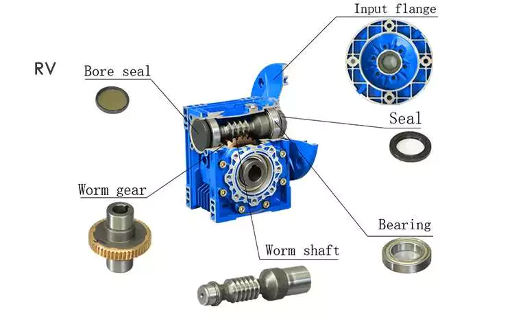
    The worm gear consists of two parts: the helical butt-jointed worm gear and the worm. The screw-butted worm gear is connected to the shaft by a helical thread. The worm gear is a variation of the six-simple machine. The worm is located in the worm wheel, which forces the worm to rotate. It also changes the plane of motion. Worm gears are usually made of steel or brass.
    Worm gear reducer gearboxes are one of the most popular types of reducer gearboxes. It provides high torque and high speed ratio in a compact package. These reducer gearboxes are used in many power transmission systems, including elevators, safety gates, conveyor belts, and medical testing equipment.
    Worm reducer gearboxes come in a variety of shapes and sizes, including parallel shaft reducer gearboxes and planetary worm reducer gearboxes. They have a high torque-to-weight ratio and are easy to maintain. They are also lightweight and relatively easy to install. This makes them an excellent choice for many applications.
    Worms can be assembled using stepped shafts, set screws or dowel pins. However, the worm is subject to a lot of thrust and must be held firmly. This could lead to a rebound. Also, the bearings may come loose and the worm may move. To avoid backlash, make sure the worm gear shaft passes through the midpoint of the worm face width.

    China ABS pa66+30gf Nylon POM Derlin super reducing running rear spur helical worm bevel ring plastic gear manufacturer     worm gearbox applicationChina ABS pa66+30gf Nylon POM Derlin super reducing running rear spur helical worm bevel ring plastic gear manufacturer     worm gearbox application
    editor by czh 2023-02-10

    China Plastic Gearbox Brushless Mini DC TGP Motor TGP01S-A130 For Toy Car Motor

    TGP01D-A130 TGP01S-A130 TGP02D-A130 TGP02S-A130

    Plastic Gearbox Brushless Mini DC TGP Motor TGP01S-A130 For Toy Auto Motor

    People of Mini DC TGP Motor


    • Small size dc equipment motor with low pace and large torque
    • Appropriate for small diameter. Minimal sound and big torque software
    • Reduction ratio: 48、120、180、220、288
    • One shaft. Modest dimensions 8een.7mm*22.3mm*60 4.5mm
    • DC plastic gear motor with low pace and large torque
    • Gear motor dimension (mm)

    Other Plastic Standard dc toy motor

    Kinds of DC Motors

    So considerably, this guidebook has broadly explained how DC motors work, the history of these mechanisms, and what they seem like. While the principles are the very same across variants, there are in fact a number of various types of DC motors, which offer you certain advantages and drawbacks above each and every other.

    This part of the manual will look at the 4 principal types of DC motor – brushless, brushed, shunt, and sequence.

    ▍Brushless DC motor

    Thanks to the advancement of strong-point out electronic engineering, a brushless DC motor is also referred to as an electronic commutation motor or synchronous DC motor, which is different from a brush motor.
    The essential difference between brushless DC motors and other sorts of motors is that they have no commutator, which is replaced by an digital servo system that can detect and modify the rotor angle.
    A Brushless DC motor has several positive aspects. The commutator employs delicate contacts referred to as “brushes”, which will use out more than time. Consequently, a brushless DC motor is a lot more sturdy and safer than the far more classic design and style.

    How does a brushless DC motor perform?

    All motors make torque by alternating the polarity of rotating magnets connected to the rotor and set magnets on the surrounding stator. At least 1 of the magnets in this team is an electromagnet, which is made of coils all around the iron main.
    In a DC motor, the DC recent flowing by means of the wire winding generates a magnetic field. Every time the armature rotates 1 hundred 80 °, the positions of the north and south poles are reversed. If the magnetic field of the magnetic pole remains unchanged, the rotor will not rotate. In buy to make torque in 1 course of the DC motor, the course of current should be reversed for every single 1 hundred 80 ° rotation of the armature.
    In the conventional brush motor, this will be done by the commutator, but in the brushless DC motor, the electronic sensor detects the angle of the rotor and controls the semiconductor swap to either reverse the present path or switch off the present at the appropriate time of rotation, so as to create torque in 1 course.

    ▍Brushed DC motors

    The Brush DC motor is the unique DC motor, which can be traced back again to the original design of Sprague. As we have reviewed in this manual, the vintage brush motor has a commutator that reverses the existing and generates unidirectional torque each and every 50 % cycle.
    Despite the fact that brushless DC motors are even now well-known in electric propulsion, cranes, paper equipment, and rolling mills, in latest many years, several brushless motors have been removed thanks to more successful brushless types.

    How does a brushed DC motor operate?

    As has been discussed in this information previously, brushed DC motors employ comfortable contacts known as ‘brushes’ to guarantee the motor rotates in a single direction. Brushed motors’ velocity can be different by the working voltage or the strength of the magnetic area.
    There are a number of distinct types of brushed DC motors, which differ depending on the link to the armature, which will be mentioned in the adhering to sections.

    Extra details

    How to Select a Gear Motor

    A gearmotor is an electrical machine that transfers energy from 1 place to another. There are many types of gearmotors. This article will discuss the types of gearmotors, including Angular geared motors, Planetary gearboxes, Hydraulic gear motors, and Croise motors. In addition to its uses, gearmotors have many different characteristics. In addition, each type has distinct advantages and disadvantages. Listed below are a few tips on selecting a gearmotor.

    Angular geared motors

    Angular geared motors are the optimum drive element for applications where torques, forces, and motions need to be transferred at an angle. Compared to other types of geared motors, these have few moving parts, a compact design, and a long life. Angular geared motors are also highly efficient in travel drive applications. In addition to their durability, they have a low maintenance requirement and are highly corrosion-resistant.
    Helical worm geared motors are a low-cost solution for drives that employ angular geared motors. They combine a worm gear stage and helical input stage to offer higher efficiency than pure worm geared motors. This drive solution is highly reliable and noise-free. Angular geared motors are often used in applications where noise is an issue, and helical worm geared motors are particularly quiet.
    The gear ratio of an angular geared motor depends on the ratio between its input and output shaft. A high-quality helical geared motor has a relatively low mechanical noise level, and can be installed in almost any space. The torque of a helical geared motor can be measured by using frequency measurement equipment. The energy efficiency of angular geared motors is 1 of the most important factors when choosing a motor. Its symmetrical arrangement also allows it to operate in low-speed environments.
    When selecting the right angular geared motor, it is important to keep in mind that increased torque will lead to poor output performance. Once a gear motor reaches its stall torque, it will no longer function properly. This makes it important to consult a performance curve to choose the appropriate motor. Most DC motor manufacturers are more than happy to provide these to customers upon request. Angular geared motors are more expensive than conventional worm gear motors.
    Motor

    Planetary gearboxes

    Planetary gearboxes are used in industrial machinery to generate higher torque and power density. There are 3 main types of planetary gearboxes: double stage, triple stage, and multistage. The central sun gear transfers torque to a group of planetary gears, while the outer ring and spindle provide drive to the motor. The design of planetary gearboxes delivers up to 97% of the power input.
    The compact size of planetary gears results in excellent heat dissipation. In some applications, lubrication is necessary to improve durability. Nevertheless, if you are looking for high speed transmission, you should consider the additional features, such as low noise, corrosion resistance, and construction. Some constructors are better than others. Some are quick to respond, while others are unable to ship their products in a timely fashion.
    The main benefit of a planetary gearbox is its compact design. Its lightweight design makes it easy to install, and the efficiency of planetary gearboxes is up to 0.98%. Another benefit of planetary gearboxes is their high torque capacity. These gearboxes are also able to work in applications with limited space. Most modern automatic transmissions in the automotive industry use planetary gears.
    In addition to being low in cost, planetary gearboxes are a great choice for many applications. Neugart offers both compact and right angle versions. The right angle design offers a high power-to-weight ratio, making it ideal for applications where torque is needed to be transmitted in reverse mode. So if you’re looking for an efficient way to move heavy machinery around, planetary gearboxes can be a great choice.
    Another advantage of planetary gearboxes is their ability to be easily and rapidly changed from 1 application to another. Since planetary gears are designed to be flexible, you don’t have to buy new 1s if you need to change gear ratios. You can also use planetary gears in different industries and save on safety stock by sharing common parts. These gears are able to withstand high shock loads and demanding conditions.
    Motor

    Hydraulic gear motors

    Hydraulic gear motors are driven by oil that is pumped into a gear box and causes the gears to rotate. This method of energy production is quiet and inexpensive. The main drawbacks of hydraulic gear motors are that they are noisy and inefficient at low speeds. The other 2 types of hydraulic motors are piston and vane-type hydraulic motors. The following are some common benefits of hydraulic gear motors.
    A hydraulic gear motor is composed of 2 gears – a driven gear and an idler. The driven gear is attached to the output shaft via a key. High-pressure oil flows into the housing between the gear tips and the motor housing, and the oil then exits through an outlet port. Unlike a conventional gear motor, the gears mesh to prevent the oil from flowing backward. As a result, they are an excellent choice for agricultural and industrial applications.
    The most common hydraulic gear motors feature a gerotor and a drive gear. These gears mesh with a larger gear to produce rotation. There are also 3 basic variations of gear motors: roller-gerotor, gerotor, and differential. The latter produces higher torque and less friction than the previous 2. These differences make it difficult to choose which type is the best for your needs. A high-performance gear motor will last longer than an ordinary 1.
    Radial piston hydraulic motors operate in the opposite direction to the reciprocating shaft of an electric gearmotor. They have 9 pistons arranged around a common center line. Fluid pressure causes the pistons to reciprocate, and when they are stationary, the pistons push the fluid out and move back in. Because of the high pressure created by the fluid, they can rotate at speeds up to 25,000RPM. In addition, hydraulic gear motors are highly efficient, allowing them to be used in a wide range of industrial and commercial applications.
    Hydraulic gear motors complement hydraulic pumps and motors. They are also available in reversible models. To choose the right hydraulic motor for your project, take time to gather all the necessary information about the installation process. Some types require specialized expertise or complicated installation. Also, there are some differences between closed and open-loop hydraulic motors. Make sure to discuss the options with a professional before you make a decision.
    Motor

    Croise motors

    There are many advantages to choosing a Croise gear motor. It is highly compact, with less weight and space than standard motors. Its right-angle shaft and worm gear provide smooth, quiet operation. A silent-type brake ensures no metallic sound during operation. It also offers excellent positioning accuracy and shock resistance. This is why this motor is ideal for high-frequency applications. Let’s take a closer look.
    A properly matched gearmotor will provide maximum torque output in a specified period. Its maximum developing torque is typically the rated output torque. A 1-twelfth-horsepower (1/8 horsepower) motor can meet torque requirements of 6 inch-pounds, without exceeding its breakdown rating. This lower-cost unit allows for production variations and allows the customer to use a less powerful motor. Croise gear motors are available in a variety of styles.

    China Basic DC Toy Motor Plastic Gearbox Motor TGP02S-A130

    TGP01D-A130 TGP01S-A130 TGP02D-A130 TGP02S-A130

    Standard DC Toy Motor Plastic Gearbox Motor TGP02S-A130

    Figures Of Fundamental DC Toy Motor

    1. One shaft.Small dimensions 40 2.2mm*40 5.5mm*23mm
    2. DC plastic gear motor with low pace and massive torque
    3. Suited for little diameter, minimal sounds, and large toque software
    4. Reduction Ratio: 48、120、180、220、288

    Application:
    Robots, Toys, Distant Control Toy autos, etc.


    Other Plastic Basic dc toy motor

    Plastic Gearbox Motor For Toy

    The toy DC motor in the photo is extremely tiny, about the dimensions of a dime, with 2 battery prospects. If the battery direct of the motor is linked to the battery, the shaft will rotate. If you reverse the leader, it will rotate in the opposite direction.
    The nylon finish cap is mounted in spot by 2 pull rings. Within the finish cover, when the motor rotates, the electrical brush of the motor transmits electric power from the battery to the commutator. (Modern DC motors are usually brushless due to the fact brushes dress in out and need to be changed.)
    The shaft fixes the rotor and commutator. A rotor is a team of electromagnets, in this scenario, 3. The armature in the motor is a group of stacked slim steel plates, and skinny copper wires are wound in the a few poles of the rotor. Both finishes of every wire (one particular for each pole) are linked to a terminal, and then every single of the 3 terminals is linked to a board of the commutator.
    The previous element of any DC motor is the stator. This motor is composed of the can human body alone plus 2 curved permanent magnets. In a DC motor, the armature is the rotor and the magnetic field is the stator.


    How does the toy motor operate?

    A quite modest motor has 2 tiny permanent magnets, a commutator, 2 brushes, 3 magnetic poles, and an electromagnet wound with metallic wires. It works in the identical way as the larger edition, but on a considerably smaller scale.

    Why Decide on our Plastic Gearbox Motor?

    •  Q: Can I get some samples very first? How shortly can I get the samples?
    •  A: Yes, we can make samples, but usually sample is not for free of charge (sample payment is charged varying from 3usd/personal computer -40 USD/pc). And the sample-creating time depends on diverse kinds, for some small motor types( 3-10days is achievable), although some gearbox motor ought to be about 25days more or less. In addition, there will be about additional 2-3 days for the supply time, and the delivery cost is not for free way too.
    • Q: Are these motor parameters from the over listing can be modified?
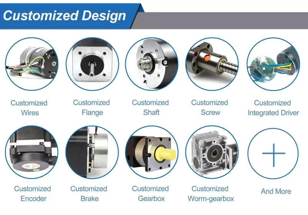
    • A: Indeed, the motor’s parameter can be customized. We can modify the motor’s operating voltage, rated speed, torque, and many others, and the motor’s shaft dimension can be modified too. We are delighted to make that modification, the much more information you give, the much more fluent our cooperation will be.
    • Q: What parameter must I provide prior to the sample making? 
    • A: Very good query. Typically we want to know the Nominal Voltage, Free-load Speed, On-load Torque, On-load Velocity, Rotation Route, Shaft Diameter, and Duration. If there is an additional specific requirement, remember to permit us know in progress, this sort of as working present limits, EMC limitations, sounds boundaries, envisioned life time, and shaft method(D-shape, multi-knurls, mounting holes, etc).
    • Q: At times I never know the specific needed parameter, how need to I decide on a appropriate product?
    • A: We can make some suggestions as prolonged as you offer your specific necessity. We need to know what type of item will be this product employed for? And what does the working issue seem like (responsibility cycles and load position)?  And how prolonged the motor’s predicted life time ? etc. Then we can make a total evaluation in accordance to that.
    • Q: Is there any Screening Report or Motor Specification when I get the sample?
    • A: Indeed, we can provide the Tests Report and Specification soon after the sample is all set. We will send out a PDF file to you. By the way, Motor Specification will be available 3-5days later on after the sample is all set.

    The Benefits of Using a Gear Motor

    A gear motor works on the principle of conservation of angular momentum. As the smaller gear covers more RPM and the larger gear produces more torque, the ratio between the 2 is greater than 1. Similarly, a multiple gear motor follows the principle of energy conservation, with the direction of rotation always opposite to the 1 that is adjacent to it. It’s easy to understand the concept behind gear motors and the various types available. Read on to learn about the different types of gears and their applications.

    Electric motor

    The choice of an electric motor for gear motor is largely dependent on the application. There are various motor and gearhead combinations available, and some are more efficient than others. However, it is critical to understand the application requirements and select a motor that meets these needs. In this article, we’ll examine some of the benefits of using a gear motor. The pros and cons of each type are briefly discussed. You can buy new gear motors at competitive prices, but they aren’t the most reliable or durable option for your application.
    To determine which motor is best for your application, you’ll need to consider the load and speed requirements. A gear motor’s efficiency (e) can be calculated by taking the input and output values and calculating their relation. On the graph below, the input (T) and output (P) values are represented as dashed lines. The input (I) value is represented as the torque applied to the motor shaft. The output (P) is the amount of mechanical energy converted. A DC gear motor is 70% efficient at 3.75 lb-in / 2,100 rpm.
    In addition to the worm gear motor, you can also choose a compact DC worm gear motor with a variable gear ratio from 7.5 to 80. It has a range of options and can be custom-made for your specific application. The 3-phase AC gear motor, on the other hand, works at a rated power of 1 hp and torque of 1.143.2 kg-m. The output voltage is typically 220V.
    Another important factor is the output shaft orientation. There are 2 main orientations for gearmotors: in-line and offset. In-line output shafts are most ideal for applications with high torque and short reduction ratios. If you want to avoid backlash, choose a right angle output shaft. An offset shaft can cause the output shaft to become excessively hot. If the output shaft is angled at a certain angle, it may be too large or too small.
    Motor

    Gear reducer

    A gear reducer is a special kind of speed reducing motor, usually used in large machinery, such as compressors. These reducers have no cooling fan and are not designed to handle heavy loads. Different purposes require different service factors. For instance, a machine that requires frequent fast accelerations and occasional load spikes needs a gear reducer with a high service factor. A gear reducer that’s designed for long production shifts should be larger than a machine that uses it for short periods of time.
    A gear reducer can reduce the speed of a motor by a factor of 2. The reduction ratio changes the rotation speed of the receiving member. This change in speed is often required to solve problems of inertia mismatch. The torque density of a gear reducer is measured in newton meters and will depend on the motor used. The first criterion is the configuration of the input and output shafts. A gear ratio of 2:1, for example, means that the output speed has been cut in half.
    Bevel gear reducers are a good option if the input and output shafts are perpendicular. This type is very robust and is perfect for situations where the angle between 2 axes is small. However, bevel gear reducers are expensive and require constant maintenance. They are usually used in heavy-duty conveyors and farm equipment. The correct choice of gear reducer for gear motor is crucial for the efficiency and reliability of the mechanism. To get the best gear reducer for your application, talk to a qualified manufacturer today.
    Choosing a gear reducer for a gear motor can be tricky. The wrong 1 can ruin an entire machine, so it’s important to know the specifics. You must know the torque and speed requirements and choose a motor with the appropriate ratio. A gear reducer should also be compatible with the motor it’s intended for. In some cases, a smaller motor with a gear reducer will work better than a larger 1.
    Motor

    Motor shaft

    Proper alignment of the motor shaft can greatly improve the performance and life span of rotating devices. The proper alignment of motors and driven instruments enhances the transfer of energy from the motor to the instrument. Incorrect alignment leads to additional noise and vibration. It may also lead to premature failure of couplings and bearings. Misalignment also results in increased shaft and coupling temperatures. Hence, proper alignment is critical to improve the efficiency of the driven instrument.
    When choosing the correct type of gear train for your motor, you need to consider its energy efficiency and the torque it can handle. A helical geared motor is more efficient for high output torque applications. Depending on the required speed and torque, you can choose between an in-line and a parallel helical geared motor. Both types of gears have their advantages and disadvantages. Spur gears are widespread. They are toothed and run parallel to the motor shaft.
    A planetary gear motor can also have a linear output shaft. A stepping motor should not operate at too high current to prevent demagnetization, which will lead to step loss or torque drop. Ensure that the motor and gearbox output shafts are protected from external impacts. If the motor and gearbox are not protected against bumps, they may cause thread defects. Make sure that the motor shafts and rotors are protected from external impacts.
    When choosing a metal for your gear motor’s motor shaft, you should consider the cost of hot-rolled bar stock. Its outer layers are more difficult to machine. This type of material contains residual stresses and other problems that make it difficult to machine. For these applications, you should choose a high-strength steel with hard outer layers. This type of steel is cheaper, but it also has size considerations. It’s best to test each material first to determine which 1 suits your needs.
    In addition to reducing the speed of your device, a geared motor also minimizes the torque generated by your machine. It can be used with both AC and DC power. A high-quality gear motor is vital for stirring mechanisms and conveyor belts. However, you should choose a geared motor that uses high-grade gears and provides maximum efficiency. There are many types of planetary gear motors and gears on the market, and it’s important to choose the right 1.
    Motor

    First stage gears

    The first stage gears of a gear motor are the most important components of the entire device. The motor’s power transmission is 90% efficient, but there are many factors that can affect its performance. The gear ratios used should be high enough to handle the load, but not too high that they are limiting the motor’s speed. A gear motor should also have a healthy safety factor, and the lubricant must be sufficient to overcome any of these factors.
    The transmission torque of the gear changes with its speed. The transmission torque at the input side of the gear decreases, transferring a small torque to the output side. The number of teeth and the pitch circle diameters can be used to calculate the torque. The first stage gears of gear motors can be categorized as spur gears, helical gears, or worm gears. These 3 types of gears have different torque capacities.
    The first stage helical gear is the most important part of a gear motor. Its function is to transfer rotation from 1 gear to the other. Its output is the gearhead. The second stage gears are connected by a carrier. They work in tandem with the first stage gear to provide the output of the gearhead. Moreover, the first stage carrier rotates in the same direction as the input pinion.
    Another important component is the output torque of the gearmotor. When choosing a gearmotor, consider the starting torque, running torque, output speed, overhung and shock loads, duty cycles, and more. It is crucial to choose a gearmotor with the right ratio for the application. By choosing the proper gearmotor, you will get maximum performance with minimal operating costs and increase plant productivity. For more information on first stage gears, check out our blog.
    The first stage of a gear motor is composed of a set of fixed and rotating sprockets. The first stage of these gears acts as a drive gear. Its rotational mass is a limiting factor for torque. The second stage consists of a rotating shaft. This shaft rotates in the direction of the torque axis. It is also the limiting force for the motor’s torque.